
Fiber Optic Installation and Maintenance Guide
As network demands continue to grow, organizations need infrastructure that can deliver higher bandwidth, lower latency, and greater transmission distances than traditional copper cabling. Fiber optic cables meet these requirements by transmitting data as pulses of light rather than electrical signals, making them an ideal choice for enterprise networks, data centers, educational institutions, healthcare facilities, and telecommunications infrastructure.
Installing fiber optic cable, however, requires more than selecting the right cable type. Proper planning, careful handling, accurate connector installation, and routine maintenance all contribute to long-term network performance. Even a small amount of dust on a connector or an excessive bend in the cable can increase signal loss and reduce reliability.
Whether you are deploying a new backbone network or expanding an existing structured cabling system, understanding what a fiber optic cable is and why it is a good option provides the foundation for making informed installation decisions.
This guide explains the essential installation practices, connector types, maintenance procedures, and testing methods that help keep fiber optic networks operating efficiently.
Understanding Fiber Optic Cabling
Unlike Ethernet cables that carry electrical signals through copper conductors, fiber optic cables transmit light through extremely thin strands of glass or plastic called optical fibers. Because light is immune to electromagnetic interference, fiber provides stable communication in environments where electrical noise can affect copper cabling.
Fiber optic cabling is generally divided into two primary categories named as singlemode and multimode fiber.
Single Mode Fiber
Single mode fiber uses a small core, typically around 9 microns, allowing a single light path to travel through the cable. This design minimizes signal dispersion and supports transmission over several kilometers, making it the preferred choice for campus networks, metropolitan infrastructure, and long-distance communication.
Multimode Fiber
Multimode fiber has a larger core that allows multiple light paths to travel simultaneously. It is commonly used for shorter distances inside commercial buildings, server rooms, and data centers where high bandwidth is required without long transmission ranges.
Modern multimode standards such as OM3, OM4, and OM5 support increasingly demanding applications, while OS1 and OS2 single mode cables are widely installed for long-distance backbone connections.
Planning Before Installation
Successful fiber optic installations begin long before the cable is pulled through a conduit or cable tray. Careful planning reduces installation time, protects the cable from damage, and simplifies future maintenance.
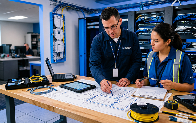
The cable route should be surveyed to identify obstacles, bending points, and environmental conditions that may affect performance. Installers should also determine whether indoor, outdoor, armored, or plenum-rated fiber is appropriate for the project.
Another important consideration is compatibility with the surrounding network. Fiber often connects backbone infrastructure to copper-based horizontal cabling, making it important to understand how it integrates with Ethernet cable installation and selection in structured networking environments.
Essential Installation Tools
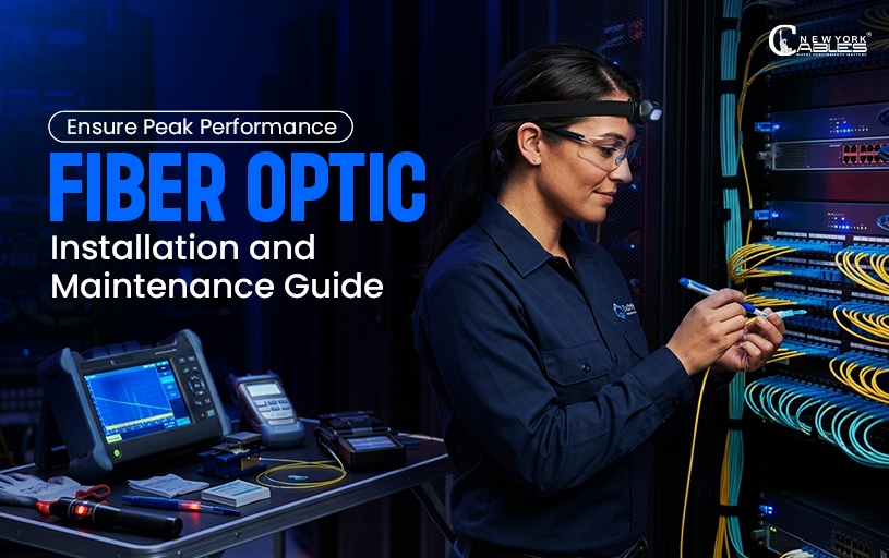
Working with fiber optic cabling requires specialized tools designed to protect delicate optical fibers while producing precise terminations.
- Fiber optic cable stripper
- Precision fiber cleaver
- Fusion splicer or mechanical splice kit
- Visual Fault Locator (VFL)
- Optical power meter
- Light source
- Fiber inspection microscope
- Cleaning pens and lint-free wipes
Using the correct tools improves connector quality while reducing insertion loss and minimizing the likelihood of future failures.
Fiber Connector Installation
The connector forms the critical interface between the optical fiber and the network equipment. A poorly installed connector can introduce attenuation, reflection, or intermittent communication even when the cable itself remains undamaged.
LC and SC Connectors
LC and SC connectors are among the most widely used fiber connectors in modern networks. LC connectors feature a compact design that supports high-density patch panels and switches, making them common in enterprise environments and data centers.
SC connectors use a push-pull locking mechanism and remain popular in telecommunications rooms and backbone installations because of their durability and ease of use.
ST, FC, and MPO Connectors
Although less common in new office installations, ST connectors continue to appear in industrial networks and some legacy systems. FC connectors use a threaded coupling mechanism that provides a secure connection in environments where vibration may be present.
For high-density applications, MPO and MTP connectors terminate multiple optical fibers within a single connector. They are frequently deployed in data centers to support high-speed parallel optical communication while simplifying cable management.
Cleaning Before Every Connection
One of the most overlooked installation steps is connector cleaning. Dust particles that are invisible to the naked eye can block light transmission or scratch the polished ferrule surface when connectors are mated.
Professional installers inspect every connector before connection and clean it using approved fiber cleaning tools whenever contamination is suspected. This simple practice significantly improves long-term reliability and supports the same quality principles used during fiber optic patch cable quality testing.
Protecting Fiber During Installation
Unlike copper Ethernet cables, optical fibers are more sensitive to excessive pulling force and sharp bends. Manufacturers specify maximum pulling tension and minimum bend radius to protect the glass fibers inside the cable jacket.
Installers should avoid twisting the cable during installation, secure cable runs using appropriate support hardware, and leave adequate service loops where future maintenance may be required.
Organized routing inside patch panels and cable trays also simplifies future inspections while reducing the risk of accidental damage.
Careful handling during installation not only protects signal quality but also reduces the likelihood of faults that later require extensive troubleshooting or expensive cable replacement.
Testing Fiber Optic Connections
Completing the installation is only the beginning. Every fiber optic link should be tested before it becomes part of an active network. Testing verifies that connectors have been installed correctly, identifies signal loss, and confirms that the cable can support its intended application.
Different testing methods provide different levels of information, so technicians often use more than one tool during installation and maintenance.
Visual Fault Locator
A Visual Fault Locator (VFL) sends visible red light through the optical fiber, making it easier to identify broken fibers, severe bends, or damaged connectors over short distances. It is commonly used during installation because it provides a quick way to locate obvious faults before performing more advanced tests.
Optical Power Meter and Light Source
An optical power meter measures the amount of light reaching the opposite end of the fiber. When used with a calibrated light source, it calculates insertion loss, allowing technicians to determine whether the installed link meets acceptable performance levels.
This method is widely used for installation acceptance testing because it provides accurate measurements of signal loss across the entire cable run.
Optical Time Domain Reflectometer
An Optical Time Domain Reflectometer (OTDR) is one of the most advanced diagnostic tools used in fiber networks. Instead of measuring only the total loss, it analyzes the entire cable by detecting reflected light, helping technicians locate splices, connector faults, sharp bends, and damaged cable sections without disconnecting the entire link.
Understanding these testing methods complements Cable Testing and Troubleshooting Guide because both copper and fiber networks require systematic verification before deployment.
Maintaining Fiber Optic Networks
Routine maintenance helps preserve network performance while extending the service life of fiber optic infrastructure. Most maintenance activities focus on preventing contamination, protecting connectors, and identifying potential issues before they affect communication.
Connectors should always remain covered with protective dust caps whenever they are disconnected. Even microscopic particles can increase insertion loss or scratch the polished ferrule surface, resulting in degraded optical performance.
Cable routing should also be inspected periodically to ensure that support brackets, cable trays, and patch panels continue to protect the cable from unnecessary stress. During maintenance, installers should verify that labels remain readable and that service loops have not been disturbed during equipment upgrades.
Preventive Maintenance Schedule
Preventive maintenance helps preserve the performance and reliability of a fiber optic network over time. Connector end faces should be inspected before every connection to prevent contamination and signal loss. Connectors should be cleaned whenever dirt or debris is suspected.
Measuring optical loss after installation and major network changes verifies link quality, and routine inspection of cable routing helps prevent damage caused by excessive bends. Keeping cable labels updated after modifications also simplifies future maintenance and troubleshooting.
Following a preventive maintenance routine reduces unexpected failures while improving long-term network reliability.nels continue to protect the cable from unnecessary stress.
Common Fiber Installation Problems
Although fiber optic cabling is highly reliable, installation errors and environmental conditions can still affect performance. Recognizing common problems allows technicians to resolve faults quickly while minimizing network downtime.
Dirty connectors remain one of the leading causes of optical signal loss. A connector may appear clean to the naked eye while still containing enough contamination to reduce transmission quality. For this reason, inspection and cleaning should become routine practices rather than occasional tasks.
Another common issue involves exceeding the recommended bend radius. Sharp bends can restrict the path of light through the fiber, creating attenuation that may not become noticeable until network traffic increases.
Improper connector installation, poorly aligned fusion splices, damaged ferrules, and excessive pulling tension during installation may also reduce network performance over time. Many of these faults resemble common networking cable issues, making a structured troubleshooting process essential regardless of whether the network uses copper or fiber.
Fiber and Copper Maintenance
Fiber optic and copper Ethernet networks share many installation principles, including proper cable management, organized labeling, and routine testing. However, fiber requires greater attention during connector handling because optical communication depends on extremely clean and precisely aligned surfaces.
Copper Ethernet installations often focus on electrical continuity, wire mapping, and proper termination. Fiber installations emphasize optical cleanliness, insertion loss, and connector inspection.
Understanding the differences between these technologies also complements Ethernet Cable Termination and Network Hardware, especially in environments where both media coexist within the same structured cabling system.
When Should Fiber Components Be Replaced?
Routine cleaning and maintenance can resolve many performance issues, but replacement becomes necessary when physical damage affects the integrity of the cable or connector.
Cracked connector housings, damaged ferrules, crushed cable jackets, excessive insertion loss after repeated cleaning, or failed fusion splices often indicate that replacement is the most reliable solution.
Replacing worn patch cords promptly also prevents recurring network interruptions and protects expensive networking equipment from avoidable connection problems.
Conclusion
A successful fiber optic installation depends on careful planning, precise connector termination, thorough testing, and consistent maintenance. Every stage of the installation process influences long-term network performance, from selecting the appropriate fiber type to protecting connectors from contamination and verifying optical signal quality.
By following industry best practices, using the proper installation tools, and performing routine inspections, organizations can build fiber optic networks that deliver reliable communication, support future bandwidth demands, and require less corrective maintenance throughout their operational life.