
Ethernet Cable Termination and Network Hardware Guide
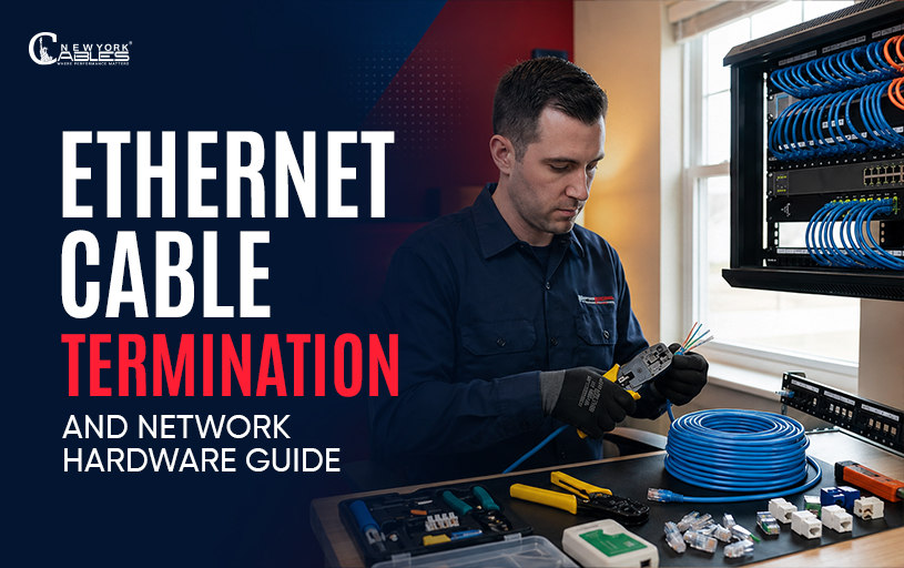
A dependable Ethernet network begins long before a cable reaches a computer, switch, or patch panel. Every connection point plays a role in carrying data accurately from one device to another. While the cable category often receives the most attention, proper termination determines whether that cable delivers the performance it was designed to provide. Ethernet cable termination is more than attaching an RJ45 connector to the end of a cable. It includes selecting the appropriate termination hardware, following the correct wiring sequence, organizing cables inside network cabinets, and verifying every connection before the network goes live. Understanding termination steps enhances Ethernet cable installation and selection because the quality of the installation is only as good as its final termination.
Understanding Ethernet Cable Termination
Ethernet cable termination is the process of preparing and connecting a twisted pair cable to networking hardware so it can transmit data between devices. Depending on the installation, the cable may terminate into an RJ45 connector, a keystone jack, or a patch panel.
Each twisted pair inside the cable has a specific purpose. Maintaining the twist of each pair until the point of termination reduces crosstalk and electromagnetic interference, helping preserve signal quality. Industry standards such as ANSI/TIA 568 recommend minimizing untwisting during termination because excessive separation can affect transmission performance, especially at higher frequencies.
A properly terminated cable also simplifies future maintenance. Organized cable routing, clear labeling, and consistent wiring standards make troubleshooting easier as the network grows.
RJ45 Connector Installation
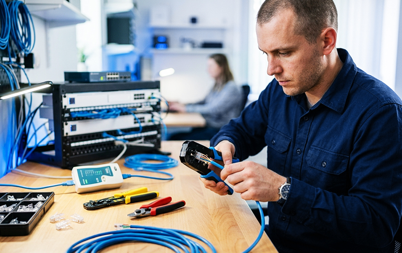
RJ45 connectors are commonly used to terminate Ethernet cables that connect directly to computers, switches, IP cameras, wireless access points, printers, and other network devices. Correct installation ensures each conductor reaches the proper contact inside the connector, allowing signals to travel without interruption.
Tools Required
Preparing an Ethernet cable requires more than a connector alone. Using dedicated networking tools improves consistency and reduces installation errors.
- RJ45 connectors compatible with the cable category
- RJ45 crimping tool
- Cable stripper
- Cable cutter
- Cable tester
- Protective strain relief boots when required
Choosing connectors that match the cable type is equally important. For example, connectors designed for solid conductors differ from those intended for stranded patch cables. Using incompatible connectors may result in unreliable electrical contact over time.
Crimping the Cable
Begin by removing only enough outer jacket to expose the twisted pairs. Straighten each conductor carefully while preserving as much of the original twist as possible. Arrange the conductors according to the selected wiring sequence before trimming them evenly and inserting them fully into the RJ45 connector.
Once every conductor reaches the front of the connector and the cable jacket sits inside the strain relief section, use the crimping tool to secure the contacts. A proper crimp creates both an electrical connection and a mechanical grip that prevents the cable from pulling free during normal use.
Understanding T568A and T568B
The two accepted wiring patterns for Ethernet termination are T568A and T568B. Both deliver identical network performance when used consistently across both ends of the cable. The difference lies only in the arrangement of the green and orange wire pairs.
Instead of viewing one as better than the other, installers should understand the purpose of both T568A and T568B wiring standards and maintain the same pattern throughout an installation unless a specific crossover configuration is required. Consistency prevents wiring errors and simplifies future maintenance.
After crimping, every cable should be tested with a cable tester to verify continuity and confirm that each conductor terminates on the correct pin.
Keystone Jack Installation
Unlike RJ45 connectors, keystone jacks are designed for permanent structured cabling. They provide a secure termination point behind wall plates, inside surface mounted boxes, and on patch panels. Rather than moving whenever equipment is connected or disconnected, the permanent cable remains fixed while short patch cords connect devices to the network.
Punch Down Process
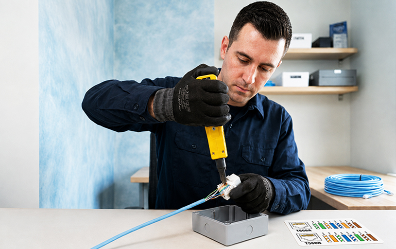
Most keystone jacks include color coded labels for both T568A and T568B wiring patterns. After removing the cable jacket, each conductor is placed into its corresponding slot before a punch down tool presses the wire firmly into the insulation displacement contacts.
The cutting edge of the punch down tool trims excess conductor automatically, producing a clean and reliable termination without stripping individual wires.
Installation Tips
Successful keystone installation depends on attention to small details. Avoid excessive jacket removal, maintain pair twists until they reach the termination slots, and prevent sharp cable bends behind the wall plate. These practices improve long term performance while supporting the recommendations covered in Ethernet cable installation best practices.
Common Mistakes
Many failed installations result from avoidable errors rather than defective hardware. Common examples include untwisting conductors too far, mixing T568A on one end with T568B on the other unintentionally, reversing wire positions, or using excessive force during punch down termination.
Inspecting each termination before closing the wall plate can prevent time consuming troubleshooting later.
Patch Panel Installation
Patch panels provide a central termination point for multiple Ethernet cable runs within a network cabinet or equipment room. Instead of connecting permanent cables directly to switches, installers terminate each cable onto a patch panel and use short patch cords to complete the connection. Proper planning protects permanent cabling while making future changes faster and more organized.
Mounting and Cable Organization
A patch panel should be securely mounted inside a network rack with enough space for cable managers above or below the panel. Incoming cables should be routed neatly, supported properly, and grouped without excessive tension. Maintaining a consistent bend radius protects cable performance while improving airflow and accessibility inside the rack.
Punch Down and Labeling
Each cable is terminated onto the rear of the patch panel using the same punch down method employed for keystone jacks. Every port should then receive a clear label that corresponds to its destination, such as an office number, workstation, or wall outlet.
Accurate labeling reduces maintenance time, simplifies equipment upgrades, and allows technicians to identify cable routes without disconnecting active network connections.
Network Rack Basics
As a network expands, managing dozens or even hundreds of cable connections becomes increasingly difficult without proper organization. A network rack provides a centralized space for networking equipment, allowing technicians to install, maintain, and troubleshoot infrastructure efficiently. Instead of scattered cables running between devices, a rack keeps equipment secure, accessible, and easy to identify.
Key Components Inside a Network Rack
A well-organized rack contains several components that work together to support structured cabling.Component
- Patch Panel: Terminates permanent cable runs and provides an organized connection point.
- Network Switch: Connects devices on the local network and directs data traffic between them.
- Cable Manager: Guides patch cords, prevents tangles, and maintains proper bend radius.
- Faceplate: Provides a clean termination point at the workstation or wall outlet.
- Patch Cord: Connects the patch panel to the network switch or end device.
Using horizontal and vertical cable managers prevents unnecessary strain on patch cords while improving airflow inside the cabinet. Organized racks also reduce the risk of disconnecting the wrong cable during maintenance or future upgrades.
Common Installation Errors
Many network performance issues originate during installation rather than after the network becomes operational. Paying attention to proper termination techniques helps avoid costly repairs and unnecessary downtime.
One of the most common mistakes is loosening the twisted wire pairs too far before termination. The twists inside an Ethernet cable help reduce crosstalk and electromagnetic interference. Untwisting more cable than necessary can degrade signal quality, particularly in Gigabit and 10 Gigabit Ethernet installations.
Another frequent problem is mixing wiring patterns unintentionally. Using T568A on one end and T568B on the other creates a crossover cable, which is unsuitable for most modern structured cabling systems unless specifically required.
Poor cable routing is another overlooked issue. Running Ethernet cables alongside electrical power lines for long distances can introduce electrical noise. Likewise, exceeding the recommended bend radius or pulling cables with excessive force may damage the conductors inside the cable jacket.
Improper labeling can also create long-term maintenance challenges. Identifying cables becomes difficult when ports and patch panels are left unmarked, increasing the time required to locate faults or replace equipment. Understanding these common networking cable issues helps installers build networks that remain easier to maintain throughout their service life.
Testing Every Termination
Completing the termination process is only part of the installation. Every cable should be tested before connecting active network equipment. Testing confirms that each conductor reaches the correct pin, verifies continuity, and detects wiring faults before they affect network performance.
Basic cable testers identify problems such as open circuits, short circuits, reversed pairs, crossed wires, and split pairs. For commercial installations, certification testers provide additional measurements including insertion loss, return loss, near-end crosstalk (NEXT), and propagation delay to verify compliance with industry performance standards.
Common Test Results
Cable testing can reveal several common faults that affect network performance. An open pair usually indicates a broken conductor or incomplete termination and often requires re-terminating the connector or keystone jack.
A reversed pair results from incorrect wire placement, while a split pair occurs when conductors are terminated in the wrong twisted pairs, both of which can be corrected by following the selected wiring standard carefully.
A short circuit is caused by conductors making unintended contact and typically requires connector inspection or replacement. If the tester reports failed continuity, inspect both cable ends for loose terminations or physical cable damage before testing again.
Following proper cable testing and troubleshooting procedures immediately after installation allows problems to be corrected before users experience slow connections or intermittent network failures.
Maintaining a Reliable Cabling System
A well-terminated network requires periodic inspection to maintain long-term reliability. Patch cords should remain neatly organized, labels should stay readable, and damaged connectors should be replaced promptly. During equipment upgrades, avoid pulling on cables directly, as repeated mechanical stress may weaken the termination over time.
When expanding a network, continue using the same wiring standard throughout the installation and document every new cable run. Consistent installation practices simplify future maintenance while reducing the likelihood of wiring errors.
Although copper Ethernet remains the preferred solution for most horizontal cabling, organizations requiring longer transmission distances or significantly higher bandwidth often integrate fiber links into their backbone infrastructure. Understanding fiber optic installation and maintenance helps network administrators plan seamless connectivity between copper and fiber networks.
Conclusion
Ethernet cable termination forms the foundation of every dependable wired network. Properly installing RJ45 connectors, terminating keystone jacks, organizing patch panels, and maintaining structured network racks all contribute to reliable data transmission and easier network management.
Following recognized wiring standards, using quality termination hardware, and testing every cable before deployment significantly reduce installation errors and improve long-term performance. Whether building a residential network or managing enterprise infrastructure, careful attention to termination details protects your investment and creates a structured cabling system that is easier to maintain, troubleshoot, and expand as networking requirements evolve.
Frequently Asked Questions
What is Ethernet cable termination?
Ethernet cable termination is the process of connecting a network cable to hardware such as an RJ45 connector, keystone jack, or patch panel so it can communicate with networking devices while maintaining proper signal integrity.
Which wiring standard should I use, T568A or T568B?
Both standards provide the same network performance when applied consistently throughout the installation. The important requirement is using the same wiring pattern on both ends of a standard Ethernet cable.
Why should every Ethernet cable be tested?
Testing confirms continuity, verifies correct wire mapping, and identifies faults such as open pairs, split pairs, or reversed conductors before the network becomes operational.
Can I terminate Cat5e, Cat6, and Cat6A using the same tools?
Most crimping and punch down tools support multiple cable categories, but connectors and keystone jacks should always match the cable category and conductor type to ensure reliable performance.
What is the purpose of a patch panel?
A patch panel provides a centralized termination point for permanent cable runs, making cable organization, maintenance, and future network expansion much easier without disturbing the installed cabling.