
Cable Testing and Network Troubleshooting Guide
Installing an Ethernet cable is only half the job. Before a network goes live, every cable should be tested to verify that it has been terminated correctly and can deliver the expected performance. A cable that appears perfectly installed may still contain wiring faults, damaged conductors, or poor terminations that cause slow speeds, unstable connections, or complete communication failures.
Cable testing identifies these problems before they disrupt users or business operations. Whether you are wiring a home network, expanding an office, or deploying a structured cabling system, testing every cable helps confirm that the installation meets performance expectations. Combining proper testing with Ethernet cable installation and selection creates a reliable infrastructure that supports high-speed networking, Power over Ethernet (PoE), and future upgrades.
This guide explains how Ethernet cables are tested, the tools professionals use, common network problems, and practical troubleshooting techniques that help maintain a dependable wired network.
Why Cable Testing Matters
A network cable can fail even when no physical damage is visible. Incorrect pin assignments, loose terminations, split wire pairs, or damaged connectors often remain hidden until devices begin experiencing connectivity issues. Testing allows these faults to be identified immediately rather than after the network is placed into service.
It is also important to understand the difference between cable verification and cable certification. Basic verification confirms that the cable is wired correctly and provides continuity between both ends. Certification goes further by measuring performance characteristics such as attenuation, near-end crosstalk (NEXT), return loss, and propagation delay to determine whether the cable complies with industry standards.
For commercial installations, certification testing is often required before a project is accepted. Following the practices used for passing a Fluke cable certification test helps ensure the cabling system performs as intended under real operating conditions.
Testing Ethernet Cables
Different testing methods evaluate different aspects of cable performance. Selecting the appropriate test depends on the installation environment, network requirements, and the level of diagnostic information needed.
Cable Testers
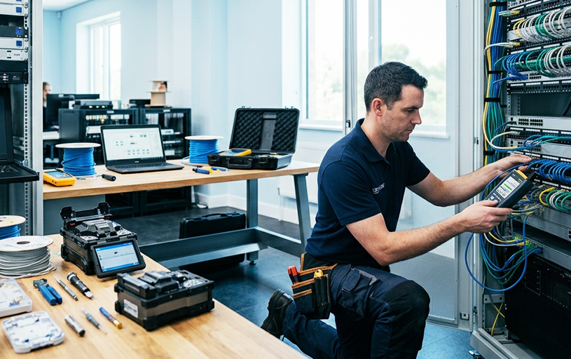
Cable testers are the primary tools used to verify Ethernet cable integrity. Basic testers check conductor continuity and wire mapping, while advanced certification testers evaluate electrical performance across the entire cable.
Testing every newly installed cable before connecting switches or workstations reduces troubleshooting time and helps identify installation defects early.
Continuity Testing
Continuity testing confirms that every conductor forms an uninterrupted electrical path between both cable ends. If a conductor is broken, disconnected, or improperly terminated, the tester reports an open circuit.
This simple test is often the first step in diagnosing cables that fail to establish a network connection.
Wiremap Testing
Wiremap testing verifies that every conductor reaches the correct pin on the opposite connector. It can detect wiring problems such as crossed pairs, reversed pairs, split pairs, and short circuits.
Incorrect wire mapping frequently occurs when connectors are terminated without carefully following the selected wiring sequence. Understanding T568A and T568B wiring standards helps installers avoid these mistakes while ensuring consistent termination throughout the network.
Power over Ethernet Testing
Power over Ethernet allows network cables to carry both data and electrical power to devices such as IP cameras, wireless access points, VoIP phones, and access control systems.
PoE testing confirms that sufficient voltage reaches the powered device and that the cable can safely support the required power level. Loose connectors, damaged conductors, or poor terminations may interrupt power delivery even when data communication appears functional.
Link Speed Verification
A successful cable test does not always guarantee maximum network performance. After installation, verifying the negotiated link speed between connected devices confirms that the cable supports the intended Ethernet standard.
For example, if two Gigabit-capable devices establish only a 100 Mbps connection, the problem may involve an improperly terminated connector, a damaged conductor, incompatible hardware, or excessive cable damage. Reviewing the quality of the Ethernet cable termination and network hardware often reveals the source of the reduced connection speed.
Common Network Problems
Even professionally installed cabling systems may experience performance issues over time. Environmental conditions, physical damage, improper handling, or installation errors can all affect network reliability. Recognizing common symptoms is the first step toward identifying their root cause.
No Network Connection
A complete loss of connectivity usually indicates a physical problem within the cabling system. Open conductors, failed RJ45 connectors, incorrect wire mapping, damaged keystone jacks, or disconnected patch panel ports can all prevent devices from establishing a network link.
Before replacing hardware, technicians should inspect the physical termination, verify cable continuity, and confirm that the wiring sequence matches the selected Ethernet standard. These systematic checks often resolve faults that might otherwise be mistaken for switch or device failures.
100 Mbps Instead of 1 Gbps
One of the most common complaints after an installation is discovering that a Gigabit network is operating at only 100 Mbps. In many cases, the cable itself is not the problem. A single conductor that is not making proper contact inside the RJ45 connector or keystone jack can prevent all four wire pairs from communicating correctly.
Since Gigabit Ethernet requires every pair to function, even a minor termination fault may force devices to negotiate at Fast Ethernet speeds.
Begin troubleshooting by inspecting both cable ends, checking the wire sequence, and testing the cable with a wiremap tester. If the cable passes, verify that the connected switch, network adapter, and patch cords also support Gigabit Ethernet.
Slow Speeds and Packet Loss
Slow file transfers, delayed application responses, and poor video call quality often indicate packet loss or excessive transmission errors. These symptoms may result from damaged cable insulation, excessive cable bends, electromagnetic interference, or poor quality terminations.
Testing the cable helps determine whether the fault lies within the cabling infrastructure or elsewhere on the network. If the cable passes electrical tests but performance problems remain, technicians should continue investigating switches, network interface cards, or software configuration before replacing the cable.
Intermittent Disconnects
Connections that repeatedly drop and reconnect are often the most difficult faults to diagnose because they may not appear during a quick inspection. Loose RJ45 connectors, partially punched keystone jacks, damaged patch cords, or cables exposed to repeated movement can all produce intermittent failures.
Examining these common networking cable issues methodically helps isolate the source of the problem instead of replacing equipment unnecessarily.
Troubleshooting Cable Terminations
Many network faults originate where the cable terminates rather than within the cable itself. Inspecting each termination point carefully often resolves connectivity problems without replacing the entire cable run.
RJ45 Connector Issues
RJ45 connectors should be checked for incomplete crimps, uneven conductor lengths, damaged locking tabs, or conductors that fail to reach the contact pins. Any loose connection increases resistance and may interrupt both data transmission and Power over Ethernet delivery.
Keystone Jack Issues
Improper punch down termination, excessive untwisting of wire pairs, or incorrect conductor placement frequently causes unreliable connections. Verifying every conductor against the selected T568A and T568B wiring standards helps eliminate these errors before replacing hardware.
Patch Panel Issues
Patch panels should be inspected for loose punch down connections, damaged ports, incorrect labeling, and poorly managed patch cords. Organized terminations make future maintenance easier while reducing the chance of disconnecting active network links during service work.
Installation Best Practices
Testing is most effective when combined with proper installation practices. Careful planning during installation reduces future troubleshooting and extends the service life of the cabling system.
- Label every cable at both ends before connecting equipment.
- Route cables through cable managers to maintain organization.
- Avoid sharp bends and excessive pulling force during installation.
- Separate Ethernet cables from electrical power wiring whenever possible.
- Test every cable immediately after termination and again before final deployment.
Following these Ethernet cable installation best practices creates a structured cabling system that is easier to maintain, expand, and troubleshoot throughout its operational life.
When to Replace a Cable
Not every network problem requires replacing the cable. However, replacement becomes the better option when repeated repairs fail to restore reliable performance or when physical damage compromises signal integrity.
Visible jacket damage, crushed cable sections, moisture exposure, failed certification testing, or recurring continuity failures are strong indicators that replacement is more practical than additional repairs. Organizations performing regular inspections also benefit from comparing results with fiber optic patch cable quality testing when evaluating mixed copper and fiber infrastructures.
For installations that extend beyond the practical distance limitations of copper Ethernet, understanding fiber optic installation and maintenance helps determine when fiber becomes the more suitable long-term solution.
Quick Troubleshooting Reference
Network issues often reveal their cause through specific symptoms. A complete loss of connection usually points to an open conductor or incorrect cable termination, making continuity testing and connector inspection the first troubleshooting steps.
If a Gigabit connection is limited to 100 Mbps, a faulty wire pair or damaged connector is often responsible, and verifying the wiremap can quickly identify the problem.
Slow network performance may result from poor termination or electromagnetic interference, so inspecting cable routing and retesting the link is recommended.
Intermittent disconnects are commonly caused by loose connectors or damaged patch cords, while Power over Ethernet (PoE) devices that fail to power on often indicate incomplete termination or conductor faults that require connector inspection and PoE testing.
By following these troubleshooting steps systematically, you can identify the root cause of most network issues before they affect overall performance. A careful approach to testing, inspection, and proper termination helps maintain a stable, reliable, and efficient network.
Conclusion
Cable testing is an essential part of every structured cabling installation. It confirms that Ethernet cables have been terminated correctly, identifies hidden faults before they affect users, and helps maintain reliable network performance over time. Combining accurate testing with quality installation practices, organized cable management, and proper termination techniques reduces downtime while simplifying future maintenance.
Whether you are installing a single Ethernet outlet or managing a large commercial network, a systematic approach to testing and troubleshooting protects the performance of your cabling infrastructure and supports dependable communication for years to come.